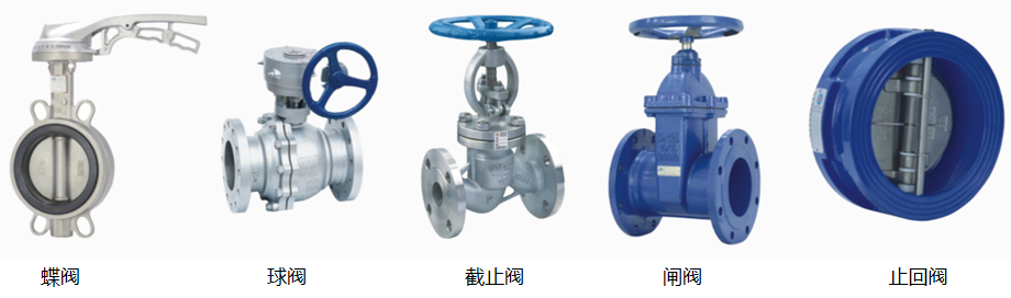
Ⅰ Valves used in water supply pipelines are generally selected according to the following principles:
1. For pipe diameters of 50 mm or less, globe valves are preferred; for diameters greater than 50 mm, gate valves or butterfly valves should be used;
2. Where flow rate or water pressure regulation is required, regulating valves or globe valves are preferred;
3. For locations requiring low flow resistance (such as on pump suction pipes), gate valves are preferred;
4. For pipe sections requiring bidirectional flow, gate valves or butterfly valves should be used; globe valves must not be used;
5. For locations with limited installation space, butterfly valves or ball valves are preferred;
6. For pipe sections requiring frequent opening and closing, globe valves are preferred;
7. For the discharge pipes of large-diameter water pumps, multi-functional valves are preferred.
Ⅱ Valves shall be installed at the following locations on water supply piping:
1. On the service connection pipe section where the residential complex's water supply piping connects to the municipal water supply main;
2. At nodes of the residential complex's outdoor looped piping network (installed according to zoning requirements); sectionalizing valves should be installed if a looped pipe section is excessively long;
3. At the starting point of branch pipes or service connection pipes (to individual buildings) taken off the residential complex's water supply trunk main;
4. On individual dwelling service pipes, at water meters, and on branch risers (at the base of the riser, and at the top and bottom ends of risers in vertical looped networks);
5. On sub-trunk mains of looped networks and on connecting pipes linking branched networks;
6. At the starting point of distribution pipes supplying individual dwellings, public restrooms, etc.; valves shall be installed on distribution branch pipes serving three or more water outlets;
7. On pump discharge pipes and on suction pipes of pumps under positive suction head (flooded suction);
8. On water tank inlet, outlet, and drain pipes;
9. On inlet and make-up water pipes for equipment (such as heaters, cooling towers, etc.);
10. On water supply pipes for sanitary fixtures (such as toilets/urinals, washbasins, showers, etc.);
11. On lines serving certain accessories—such as automatic air release valves, pressure relief valves, water hammer arrestors, pressure gauges, and hose bibbs—as well as upstream and downstream of pressure reducing valves and backflow preventers;
12. Drain valves should be installed at the lowest points of the water supply piping network.
Ⅲ Check valves should generally be selected based on factors such as their installation location:
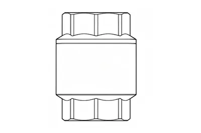
1. Swing-type, ball-type, or shuttle-type check valves should be selected when the water pressure upstream of the valve is low;
2. Check valves equipped with closing springs should be selected when strict sealing performance is required after closure;
3. Rapid-closing silent check valves or slow-closing check valves with damping devices should be selected when it is necessary to mitigate water hammer caused by valve closure;
4. The disc or core of the check valve must be capable of closing automatically under the action of gravity or spring force.
Ⅳ Check valves shall be installed on the following sections of water supply piping:
On the service entry pipe; on the inlet pipe of a sealed water heater or water-using equipment; on the discharge pipe of a water pump; and on the discharge pipe section of water tanks, water towers, or elevated reservoirs that share a common pipe for both inlet and outlet flows.
Note: Sections of piping equipped with backflow preventers do not require the installation of additional check valves.
Ⅴ Air release devices shall be installed at the following locations in water supply piping:
1. For intermittently used water supply networks, automatic air release valves shall be installed at the network's terminal ends and highest points;
2. For sections of the water supply network with significant undulations where air may accumulate, automatic air release valves or manual air release valves shall be installed at the high points (peaks) of such sections;
3. For pneumatic water supply systems using automatic air-replenishing pressure tanks, automatic air release valves shall be installed at the highest points of the distribution network.
Ⅵ Advantages and Disadvantages of Different Valves
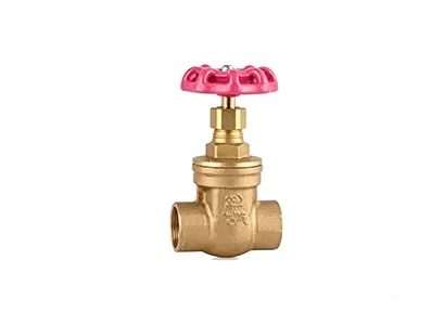
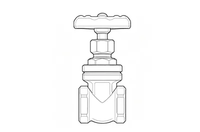
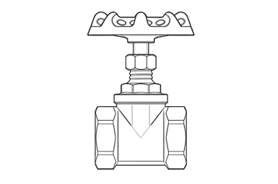
1.Gate Valve: A gate valve is a valve in which the closing element (the gate) moves perpendicular to the axis of the flow passage. It is primarily used in pipelines to shut off the flow—meaning it is operated in either the fully open or fully closed position. Generally, gate valves should not be used for flow regulation. They are suitable for a wide range of conditions, including low-temperature/low-pressure and high-temperature/high-pressure applications, and are available in various materials. However, gate valves are generally not used in pipelines transporting media such as slurry.
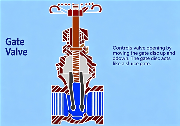
Advantages:
① Low fluid resistance;
② Low torque required for opening and closing;
③ Can be used in ring-network pipelines where the medium flows in both directions (i.e., flow direction is unrestricted);
④ When fully open, the sealing surfaces are subject to less erosion by the working medium compared to globe valves;
⑤ Relatively simple structural design and good manufacturability;
⑥ Short face-to-face dimension (compact structural length).
Disadvantages:
① Large overall dimensions and high opening lift, requiring significant installation space;
② Significant friction on sealing surfaces during opening and closing; prone to galling or scoring, especially at high temperatures;
③ Generally features two sealing surfaces, which complicates machining, lapping, and maintenance;
④ Long opening and closing times.
2.Butterfly Valve: A butterfly valve is a type of valve that uses a disc-shaped closure element, rotating approximately 90° back and forth, to open, close, and regulate fluid flow.
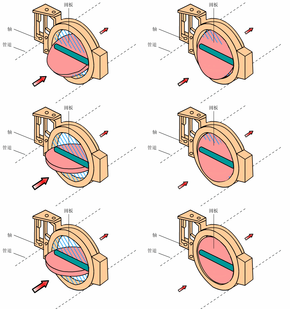
Advantages:
① Simple structure, compact size, light weight, and material efficiency; suitable for large-diameter valves;
② Rapid opening and closing; low flow resistance;
③ Suitable for media containing suspended solid particles; depending on the strength of the sealing surface, it can also be used for powdery and granular media. It is applicable for bidirectional opening/closing and regulation in ventilation and dust removal pipelines, and is widely used in gas and water piping systems across metallurgy, light industry, electric power, petroleum, and chemical sectors.
Disadvantages:
① Limited flow regulation range; once the valve opens to 30%, the flow rate reaches over 95% of capacity;
② Due to structural and sealing material limitations, it is unsuitable for high-temperature or high-pressure pipeline systems; generally limited to operating temperatures below 300°C and pressure ratings below PN40;
③ Sealing performance is inferior to that of ball valves or globe valves, so it is used in applications where sealing requirements are not extremely stringent.
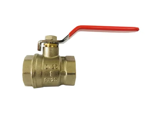
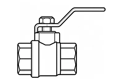
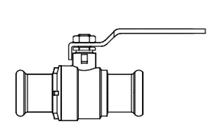
3.Ball Valve: Evolved from the plug valve, the ball valve features a spherical closure element; opening and closing are achieved by rotating the sphere 90° around the valve stem axis. In pipelines, ball valves are primarily used to shut off, distribute, and change the flow direction of media; ball valves designed with V-shaped openings also offer excellent flow regulation capabilities.
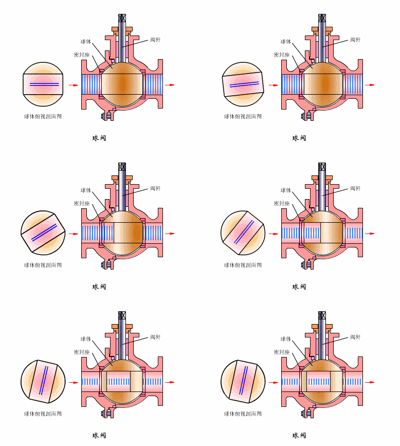
Advantages:
① Lowest flow resistance;
② Does not jam during operation (even without lubrication), making it reliable for use with corrosive media and low-boiling-point liquids;
③ Capable of achieving a complete seal across a wide range of pressures and temperatures;
④ Enables rapid opening and closing; certain designs have actuation times as short as 0.05–0.1 seconds, making them suitable for automated systems in test rigs. Rapid opening and closing operations occur without shock or impact;
⑤ The spherical closure element can automatically position itself at the limits of travel;
⑥ Reliable sealing is achieved on both sides of the closure element;
⑦ In the fully open and fully closed positions, the sealing surfaces of the ball and seat are isolated from the medium, preventing erosion of the sealing surfaces by high-velocity flow;
⑧ Compact and lightweight, it is considered the most suitable valve design for cryogenic service;
⑨ The symmetrical valve body—particularly the welded body design—effectively withstands pipeline stresses;
⑩ The closure element can withstand high differential pressure during closing;
⑪ Fully welded ball valves can be buried directly underground, protecting internal components from corrosion; with a service life of up to 30 years, they are ideal for oil and natural gas pipelines.
Disadvantages:
① The primary seat sealing material is PTFE (polytetrafluoroethylene). While PTFE is chemically inert and offers a low coefficient of friction, stable performance, resistance to aging, a wide operating temperature range, and excellent sealing capabilities, its physical properties—such as a high coefficient of thermal expansion, susceptibility to cold flow, and poor thermal conductivity—dictate specific design requirements for the seat seal. Consequently, if the sealing material hardens, sealing reliability is compromised. Furthermore, PTFE has a limited temperature rating and can only be used at temperatures below 180°C; exceeding this limit causes material degradation. In practice, for long-term applications, usage is generally avoided at temperatures above 120°C.
② Its flow regulation performance is inferior to that of globe valves, particularly in pneumatic (or electric) versions.
Other Brass Valves from JKL Brass Valve