
Can't understand the water supply and drainage system diagram? Don't worry, let's get straight to the essentials.
Step 1: Distinguish the system
In the previous issue, we talked about the codes for water supply and drainage pipes. When you get the drawings, don't look at anything else first; check the title block of the design drawing for the pipe codes to distinguish the system type: water supply/sewage/wastewater/rainwater/condensate water.
1. Water Supply System
Pipe codes: J, JL
Main function: Daily tap water supply to communities, buildings, and households, as well as kitchen and bathroom water supply. The overall direction is mostly from top to bottom, with layered household water supply.
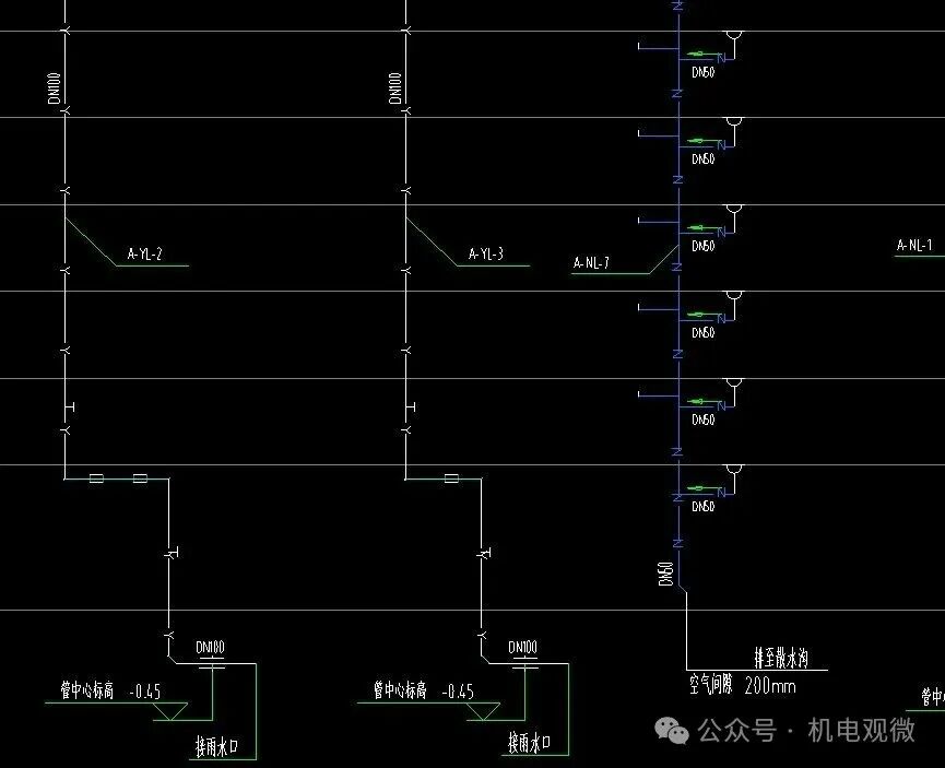
2. Sewage/Wastewater/Rainwater/Condensate Drainage System
Pipes are mostly thick or dashed lines, core codes: W, F, Y, N
Main function: Discharge of sewage from bathrooms, kitchens, balconies, roof rainwater, and air conditioning condensate water.
If you need detailed drawings, leave a comment.
Step 2: Look at the Riser
In the water supply and drainage system diagram, the vertical lines are the risers, which are the "backbone" of the water pipes for the entire building. The horizontal branch pipes are all connected from the risers.
Understand the system diagram: Three key points:
1. Check the numbering: JL-1, WL-2, representing water supply riser No. 1 and drainage riser No. 2. Pipes with the same number run through all floors.
2. Look at the arrows: The arrows on the risers indicate the pipe direction, pointing upwards to the roof and downwards to the basement or outdoor network.
3. Check the branch pipes: The horizontal pipes branched from each floor's riser are the household branch pipes, specifically connecting each household's kitchen, bathroom, balcony water supply, and drainage points.
Step 3: Quickly recognize common symbols without memorizing
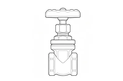
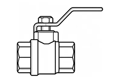
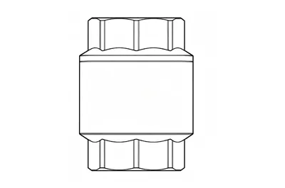
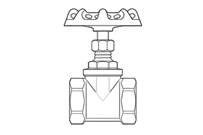
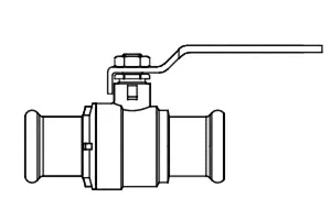
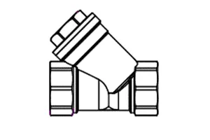
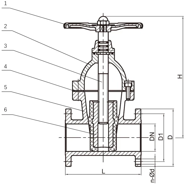
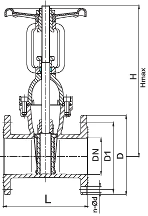
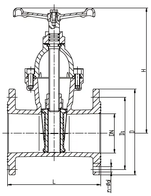
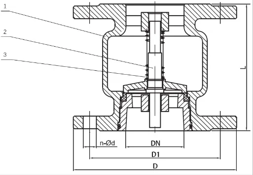
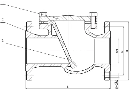
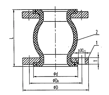
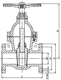
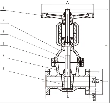
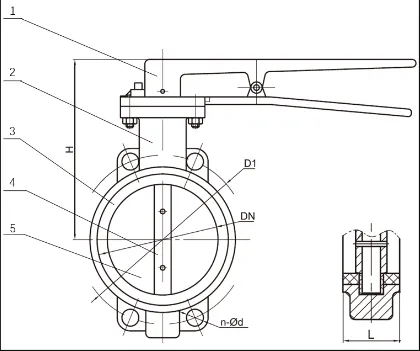
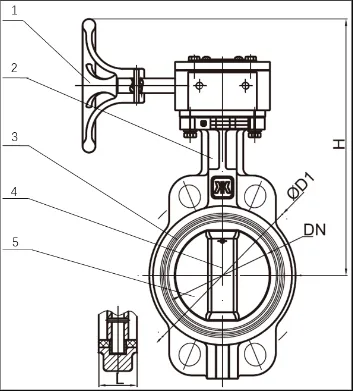
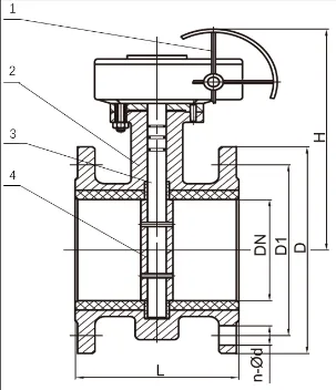
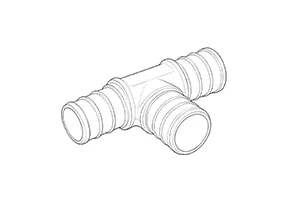
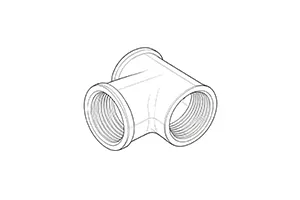
Remember common symbols: valves, floor drains, cleanouts, traps, water meters, water tanks, tees/crosses, etc.
Step 4: Focus on two key numbers to understand pipe parameters
The numbers on the system diagram are the core basis for quantity calculation. Just focus on two types:
1. Pipe diameter numbers
Common labels: DN20, DN50, De110
Used to distinguish pipe sizes.
2. Elevation numbers
Common labels: ±0.00, 3.00m, 6.00m
Quickly determine the pipe installation method: ceiling, floor, or wall installation.
Step 5: Compare the system diagram with the plan, thoroughly understanding the drawings
Looking at the system diagram or the plan alone is prone to errors. Combining the two gives a complete logic:
System diagram: Look at the vertical direction, riser connection methods, floor pipe layout relationships, and overall water flow logic.
Plan: Look at the horizontal pipe positions, specific points in kitchens and bathrooms, and the actual positions where pipes penetrate walls and beams.
Diagram reading tips, directly copy
First look at the header to determine the system, then find the riser to locate up and down,
Check the direction of horizontal pipes on each floor, recognize symbols for valves and accessories,
Focus on elevation and diameter numbers, match entry and exit points to the plan.
What pitfalls have you encountered in practice? See you in the comments; let's learn together!
Other Brass Valves from JKL Brass Valve